In this blog we explore how a gateway (a router) present in a LAN handles routing to the outside of this network and use redirection to enhance this operation.
lab setup
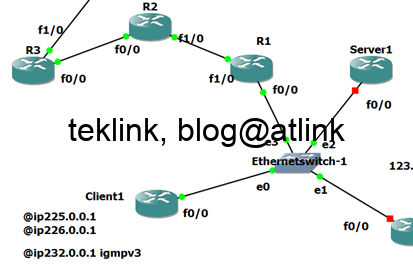
Our lab setup is 3 routers: R1, R2 and R3, in addition to 2 PC: PC1 and PC2. In this lab, PC1 tries to interconnect to PC2.

Routers R1, R2 and R3 have interfaces (f0/0) in the same network 123.0.0.0 and belong the same broadcast domain Vlan204. This is to test redirection that we put all the routers on the same L2 network.
To allow PC1 to connect to PC2, static routing is configured on routers R1, R2 and R3. On router R1, PC1 and PC2 network are not connected and one hop away. Static route to PC1 is configured with a nexthop pointing to f0/0 interface of R2. The same for PC2, the configured nexthop is the IP address of the f0/0 interface of R3.
Remember that we try to build this routing path from PC1: PC1 to R2 to R1 to R3 and last to PC2. You agree that the simple way is not to include R1 in this path…
To confirm our configuration using the CLI (Commande Line Command), we check at R2 that PC2 network is reachable via R1 interface inter vlan204 network using the command show ip cef.

We check the same at R3 that PC1 network is reachable via the R1 interface in network 123.0.0.0.

A packet to reach PC2 from PC1 is first forwarded to R2 f1/1 interface in network 12.0.0.0. At R2, a route lookup is done against the destination of PC2. The configured static route is matched in this table and packet sent to the next hop. Cef forwarding confirms this routing. At R1, the packet is received and its destination looked up in the routing table and sent to R3 that forward it to PC2. The return traffic (reply) followes the same path…
debug
let’s confirm our understanding of the operation of our setup using debug commands at each router. Let’s recall that the routing table called also local routing table or RIB (Routes Information Base) is different from Cef (Cisco Express Forwarding). Learnt routes are first put in routing table (RIB) and next in forwarding table (CEF). In CEF the forwarding that helps effectively send the packet is specified which is not necessary the case in routing table for the sample reason that forwarding a destination may require the usage of many routes to find the actual output interface. Think about routes that use an intermediate address as a nexthop (static routing, BGP, etc.). This intermediate address needs to be resolved to an output interface and IP in the same connected network before the routing is done, the new forwarding rule is added to CEF and packet sent…
A “debug ip cef input” on R2 shows how forwarding is done (not only routing information if we debug RIB. An added routing information does not necessary hint on the effective forwarding of the packet itself). We check that the packet (ping echo) send by PC1 (ip address 12.0.0.1) towards PC2 (ip address 23.0.0.1)

The same debug on R3 shows that received the same packet from PC1 to PC2

The same thing done on R1 shows that the packets from R2 and R3 are being received by R1 too

the debug commands showed us CEF in action and that packets from PC1 to PC2 were processed but does not hint on the order. We have two possibilities: 1) the packet travelled from R2 to R1 and then to R3 doing 3 hops, or 2) the packet travelled from R2 to R1 and R3 before it reaches PC2 doing only 2 hops. Let’s confirm using a packet capture tool (Wiershark)
packet capture
we need to know more details about this traffic to answer the previous question whether the packet from PC1 to PC2 has done 2 or 3 hops before reaching its destination. For this purpose let’s find what ethernet mac addresses were used.
in vlan204, in the packet from PC1, the source mac address is set to R1

in the packet from pc-2, the destination mac is set to R1 too

The ARP table of R1 shows the mac address ip address correspondence in vlan 204 and confirms our findings that the packet goes through R1 and thus our first scenario. Let’s recall that ARP is the procedure in Ethernret network by which hosts, routers, etc. learns the MAC addresses match to the IP addresses they use to reach their destinations. This information is crucial to encapsulate at layer two the IP packet into the Ethernet frame.

problem statement
But R1 is not on the optimal path between R2 and R3! the packet does more hop the reach the destination evenif R2 is directly connected to R3 in the vlan204 network…
Traffic from R2 must cross 123.0.0.0/24 network twice to reach PC-2 behind R3 which is another problem if we consider how NOT optimized is the usage of the network and ressources.
icmp redirect
Why in this case, the ip icmp redirect is not into play? R1 could hint R2 on a better gateway that is R3 to reach PC2 network… a show ip traffic shows in ICMP section that no redirects were issued at R1 level.

The show command confirms that NO redirects were sent (nor received)
We checked also the version of these routers to confirm they support this feature and that there’s no bug related to this feature.

We confirmed that the ip redirects are also enabled locally on the ip interfaces

and globally. Let’s note that the feature is named ip icmp redirect host and not router!

Let’s send a ping directly from R2 and enable a debug icmp

Now we check that a redirect messages was received from R1 for 23.0.0.1 and hints him to use the gateway R3 instead. The difference is that the traffic is generated within the same network the vlan204 network.
On R1 we check now using the show command that 3 redirects were sent (already received by R2 as checked with the previous debug command)

And nothing happens on R3 (the second gateway!) which is very important…
What is the most suitable option? Have R3 to send the ip redirect (to himself)? Or keep it by R1?
Even if R1 sends redirection messages, the the effective path PC1 packets take does not change
a trace route from PC-1 shows that the path always includes R1

Router as a Host option
Let’s disable ip routing on R2 so emulate the function of a host, and configure a default gateway towards R1, and see

Now the redirection is installed

and confirmed by packets being sent to R3 mac address directly instead of R1’s (redirect, ARP, echo request, reply)

NAT
We enable the ip routing on R2 and configure it to NAT PC1 traffic now

R1 still sends ip redirects

But these packets do not get processed by R2
at least the debug ip icmp returns nothing…
a debug ip nat shows that packets from R1 get Nated too

On the wire (R1 and R2 link) we check that redirects are sent

Traffic from R1 (redirects) gets also Nated, passes through R2!
And redirects are being received by PC-1

A regular traffic from R1 (marked by a packet size of 1500 bytes) did not get passed through R2 evenif Nat sessions are still active (which is another problem)

need to see the RFC
To understand our findings let’s have a walk by the RFC 792 that describes icmp redirection implementation. The RFC states clearly that:

Taking into consideration information from the RFC, here’s what happened in our netowrk
- R1 checks the packet is coming from 123.0.0.0/24 (source ip address)
- it checks its routing table and found a better gateway towards R3
- the packet source ip and R3 fa0/0 interface are on the same subnet
- R1 sends a redirect message to R2
A full redirect message received by R2 is shown in this figure:

As conclusion
ip icmp redirection is aimed for hosts in the same network as the gateway and not for packet with ip route source option.
trying to simulation this feature on R2 we’ve observed the following behavior:
- when ip routing is disabled we’ve seen that R2 does not use ip redirects (icmp) it receives… evenif they’re now generated by R1
- when using NAT, it is not working neither evenif R1 generates redirects that suprisingly get NATed too. If we consider the first ipv4 header, why this packet get Nated? is the identification field, in the ip packet, used in overload Nat to distinguish and identify Nat sessions from the same host? in this case why does R2 consider the embedded ipv4 packet? instead of the outer one…
Something needs more clarification about operation of redirection and NAT.


